
Technical guide to gas metering and calibration
Based on Inotech’s training. German-engineered gas and water meter test systems since 1992, trusted in more than 70 countries. Now available in Egypt through Infinity Egypt, ZERA’s exclusive partner.
The physics behind every gas meter test
The physics of gas measurement, sonic nozzles versus reference meters, the calibration room, industrial and high-pressure rigs, and pressure regulator testing, in one working guide.
InletSlow gas at steady pressure and temperature. The upstream state is measured here.
ThroatGas reaches the speed of sound. The nozzle is choked and its mass flow is fixed.
DiffuserPressure recovers on the way to the vacuum pump that keeps the nozzle choked.
- < 0.18%
- Single nozzle calibration possible in Inotech’s laboratory
- < 0.25%
- Complete reference meter rig possible
- < 5 min
- Full rotary meter production test with laser pulse detection
- 65 bar
- Largest natural gas closed loop shown, at 30,000 m³/h
Every cubic metre of gas that is billed has passed through a meter, and every meter earns its accuracy on a test rig. This guide explains how those rigs work, from household meters to transmission pipelines.
Part 1 of 4
The theory of gas meter testing
Why gas is awkward to measure, and the two reference principles that every test rig is built on.
Why gas is harder to measure than water
Four physical facts shape the design of every gas test rig.
Water is close to incompressible, so a litre at the meter is a litre at the reference. Gas volume moves with every millibar and every tenth of a degree.
Pressure and temperature are part of the volume measurement. Readings taken at different conditions must be converted before they can be compared.
Density and viscosity set the Reynolds number and the meter’s response. An error curve obtained with air does not automatically apply to natural gas or hydrogen.
Mechanical gas meters run on very little force. Bearing friction, pulsation and installation effects can materially change the result.
A leak removes gas from the measured flow. Gas benches need far stricter leak control than water benches, more so with natural gas or hydrogen.
Converting volume to base conditions
Two volumes can only be compared at the same state. This conversion sits under every gas meter test.
V is volume, p absolute pressure, T absolute temperature and Z the compressibility factor. Subscript m marks measured conditions and b base conditions. Z is close to 1 at low pressure, but it still belongs in the measurement model.
What a small sensor error costs
Reference principle one: critical flow nozzles
A sonic nozzle does not measure flow. It defines one.
When gas reaches the speed of sound at the narrowest point of a critical flow Venturi nozzle, the throat, the nozzle is choked. From that point the mass flow depends only on the throat geometry, the gas properties and the upstream stagnation pressure and temperature.
Within the choked range, nothing that happens downstream changes the nozzle’s mass flow. That is what makes nozzles such stable references. Repeatability still depends on steady upstream conditions and an unchanged throat.
qm is mass flow, C the discharge coefficient, C* the critical flow function of the gas, A the throat area, p0 and T0 the upstream stagnation pressure and temperature, and Rs the specific gas constant.
Linked to the throat Reynolds number under ISO 9300. Near 0.99 for a toroidal-throat nozzle, confirmed by calibration.
Depends on the actual gas and its state, so the gas composition must be known.
Contamination or condensation at the throat changes the reference.
Staying choked
For an ideal gas with a heat capacity ratio of 1.4, the theoretical critical pressure ratio is 0.528. A Venturi diffuser recovers much of that pressure, so a well-designed nozzle stays choked at back pressure ratios of around 0.8 to 0.9. The two figures describe different pressure locations: the first at the throat, the second at the nozzle outlet. A vacuum pump or blower downstream has to hold a sufficient ratio for every active nozzle.
How a nozzle rig is laid out
- 1Air intakeFiltered air from the conditioned room
- 2Meters under testPressure and temperature measured
- 3PlenumLow velocity. p0 and T0 measured
- 4Nozzle bankParallel nozzles, each with its own valve
- 5Vacuum pumpHolds the pressure ratio, then exhausts
Simplified suction-operated nozzle rig. Block-and-bleed valve arrangements verify that every inactive nozzle stays leak-tight during a test.
Selecting flow with a nozzle bank
One nozzle gives one flow. A bank of nozzles in parallel, graded so that each is double the one before, gives many. With n nozzles there are 2n − 1 usable combinations. The points are discrete: changing the plenum pressure shifts them, and a stable gas temperature holds them in place.
Build a flow from a nozzle bank
Try itOpen and close the valves. The smallest nozzle is 100 L/h and each one doubles, as in the training example.
- Selected flow
- 0 L/h
- Flow points available
- 15
- Bank maximum
- 1,500 L/h
Reference principle two: reference gas meters
A calibrated meter in series with the meter under test.
The same gas passes through both meters, but at different positions, so pressure and temperature differ between them. The rig measures the gas state at both positions and corrects for the difference before judging the meter.
- 1Laboratory airDrawn in through a flow conditioner
- 2Meter under testPressure and temperature measured
- 3Reference branchLow, medium or high flow meter. Pressure and temperature measured
- 4BlowerSpeed-controlled, then exhaust
Correcting the reference volume
Position 1 is the reference meter and position 2 the meter under test. Vref,c is the reference volume converted to the conditions at the meter under test. A positive error f means the meter indicates more volume than the corrected reference.
Without the conversion, pressure loss and temperature change between the two positions would be reported as meter error. The calculator shows how much that matters.
See what the correction does
Try itChange any value. The compressibility ratio is taken as 1, which is reasonable near atmospheric pressure.
Controls that protect the result
-
- Start and stop both readings together, using synchronised pulse counters.
- Hold the flow steady for the whole comparison window.
- Provide straight lengths and flow conditioning at both meter positions.
- Account for reference uncertainty and drift between recalibrations.
- Calibrate on the actual test gas, or apply a justified correction.
Nozzles or reference meters?
Not rivals so much as links in one calibration chain. A reference meter used for service checks may itself have been calibrated on a nozzle rig.
Critical flow nozzlesFix a mass flow
Strengths
- No moving parts, long-term stability
- Unaffected by downstream disturbance while choked
- Highly repeatable test points
Trade-offs
- Discrete flow points only
- High pressure drop, large vacuum pumps
- Gas composition must be known
Best for: automated verification, production testing, laboratory references.
Reference gas metersIndicate a volume
Strengths
- Continuous flow adjustment
- Low pressure drop, modest blower
- Suits portable and compact rigs
Trade-offs
- Wear and drift, regular recalibration
- Sensitive to pulsation and installation
- State correction needed between positions
Best for: portable and stationary rigs, in-service checks, wide flow coverage.
The full comparison
| Criterion | Critical flow nozzles | Reference gas meters |
|---|---|---|
| Reference quantity | Mass flow, calculated from calibrated throat geometry, gas state and gas properties | Volume, indicated by a calibrated meter |
| Flow selection | Discrete nozzle combinations. Plenum pressure shifts the points | Continuous, with a control valve and blower speed |
| Long-term stability | No moving parts. Long intervals between calibrations under suitable conditions | Mechanical wear and drift. Regular recalibration needed |
| Downstream effects | None, as long as the nozzle stays choked | Pulsation and installation effects must be controlled |
| Pressure and power | High pressure drop. Larger vacuum pumps and more electrical power | Low pressure drop. A more modest blower |
| Gas dependence | Gas properties and composition enter the flow calculation | Calibration or correction must match the gas used |
| Main uncertainty sources | Nozzle calibration, upstream sensors, gas model, throat condition | Reference calibration, drift, state corrections between positions |
What a small sensor error costs
Part 2 of 4
Domestic benches and the calibration room
How the same core technology is configured for four kinds of user, and why the room it stands in is part of the measurement.
Three capacity tiers, one flow scale
Domestic rigs up to 10 m³/h, commercial up to 40 m³/h, industrial from 1,000 to 10,000 m³/h.
Where each equipment family sits
Flow ranges as stated in the training. Bars that fade in from the left have a stated upper limit only.
- Meter rigs at low pressure
- Regulator rigs
- High-pressure closed loops
Four users, four bench designs
The bench is configured around who operates it and why.
Cells with 6, 12 or a custom number of positions for diaphragm or ultrasonic meters. Automated staging, smart meter communication and internal valve tests.
Priority: throughput, up to three shiftsSonic nozzle benches covering G1.6 to G25, for example six positions for G1.6 to G6 and three for G10 to G25. Operator workstation, optional climate chamber.
Priority: lowest uncertaintyCompact bench, for example three domestic positions plus one up to G25 (40 m³/h), paired with a leak test station.
Priority: sample and batch testingDedicated benches that communicate directly with the meter’s sensor electronics. Air, or natural gas in a closed loop.
Priority: a medium that suits the meterFor utilities, sample testing is also the route to extending verification validity. The training cited in-service periods of 10 to 24 years achieved this way.
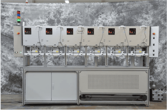
Production bench with valve testing.
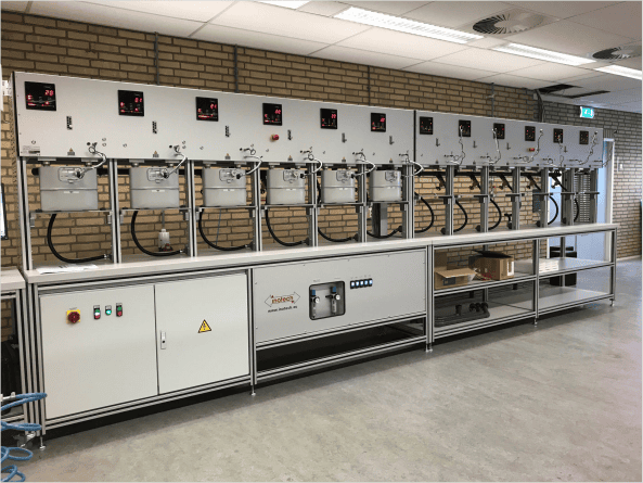
Laboratory calibration bench
Preparing meters that come back from the field
-
1
Purge
An optional suction manifold and air-flushing system evacuates residual gas from used meters at the test positions.
-
2
Exhaust safely
A dedicated explosion-proof side-channel blower carries the purged gas to an exhaust outlet.
-
3
Check tightness
A movable water bath rises around the clamped, pressurised meter so any leak shows as bubbles.
The calibration room is part of the instrument
Requirements set out in the training, citing PTB testing instructions, volume 29.
An atmospheric bench draws room air through the meters, so the state of the room enters the measurement directly.
- 22 °C ± 5
- Usable room temperature
- < 2 °C
- Change over 24 hours
- < 0.2 °C
- Change during a measurement
- 12 hours
- Wait after any switch-off. Avoid overnight switch-off
- 10 hours
- Meters in the room before testing
- 2 doors
- Double-door entrance, no direct sunlight
- Air quality
- Clean and dust free, with stable humidity
Why the 0.2 °C limit is so tight
Part 3 of 4
Industrial rigs and high pressure
Rotary, turbine and ultrasonic meters bring flows in the thousands of cubic metres per hour and bodies that need a crane.
The iTF series
Three aims: match the test line to the meter, cut handling time, cut measurement time.
Inotech’s iTF family covers 0.5 to 6,500 m³/h. The compact versions use several special rotary reference meters working in parallel, with automatic reference selection. Because rotary references do not need the long straight inlet and outlet runs that turbine references do, the training describes a 6,500 m³/h rig fitting in a footprint of about 3 m by 3 m.
| Rig | Flow range, m³/h | Reference technology | Notes |
|---|---|---|---|
| Compact iTF family | 0.5 to 6,500 | Multiple rotary reference meters in parallel | Smallest footprint. iTF3000 and iTF4000 shown as examples |
| iTF1600-1-A | 0.5 to 1,600 | Sonic nozzles only | Immune to meter pulsation. Needs vacuum pumps and more electrical power |
| iTF6500-1-A | 0.5 to 6,500 | Turbine reference meter | For turbine and rotary meters. Needs straight pipe runs |
Laboratory benches sit below these: one design covers G1.6 to G400 with a revolver clamping system, and a basic sonic nozzle design covers G10 to G65.
Clamping without bolts
Five pipe diameters on a rotating drum cover G1.6 to G400, up to 650 m³/h. Pneumatic clamping replaces flange bolts and brings changeover down to minutes.
The meter is lowered by crane onto a wheeled carriage. Actuators pull the pipework against the flanges to seal.
Quick-connect terminals for pressure, temperature and pulse sensors sit on a flexible arm beside the meter, with a local status display.
Still the right answer for unusual flanges or occasional tests.
Laser pulse detection: the slow point made fast
Reading the rotors directly instead of waiting for the index.
At minimum flow, the rotors of a rotary meter turn slowly. A conventional pickup reading the meter’s index has to wait a long time to collect enough pulses. The laser method aims a beam through the sight glass onto the rotors themselves. Each passing rotor edge produces a pulse, so resolution no longer depends on the index.
Time on the bench
Figures cited in the training.
One meter, minimum flow point only
Complete test: leak check plus Qmax, 0.2 Qmax and Qmin
Laser pulse detection on a rotary meter, redrawn from the training. Inotech states that the minimum flow measurement itself falls from minutes to seconds.
Closed loops: the real gas at the real pressure
A meter’s error curve shifts with the gas it measures and the pressure it runs at.
A closed loop removes the guesswork by circulating the service gas through the meters and the reference. In normal operation the same gas is reused, with no continuous consumption or discharge.
- 1CompressorSupplies the pressure ratio, and adds heat
- 2Cooler and filterHold the gas state steady
- 3Meters under testOn the actual service gas
- 4Plenump0 and T0 measured
- 5Nozzle bankDischarges to the low-pressure side
Simplified closed-loop nozzle rig for natural gas or hydrogen. Temperature control matters because the compressor warms the loop, and a drifting upstream state would shift the reference flow.
Handling flammable gases
Hazardous area classification and gas detection.
Relief and vent connections built into the loop.
Filling, purging and inerting follow set procedures.
Materials resistant to embrittlement, and suitable seals.
High-pressure calibration
EN 12261, the European standard for turbine gas meters, draws its line at 4 bar. Below it, calibration with air at atmospheric pressure is accepted. Above it, the meter is calibrated at pressure. High-pressure closed loops exist to do exactly that.
High-pressure loops
Flow capacity in m³/h, with operating pressure.
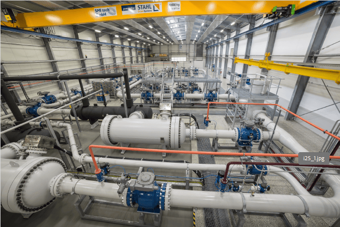
-
- Compressed air loops avoid explosive gas altogether, which lowers the safety cost of the facility.
- Natural gas loops serve transmission meters that must be calibrated on the pipeline medium.
- Bidirectional loops calibrate a meter in both flow directions without removing and refitting it. They suit storage connections, network interconnectors and transfer points where flow reverses.
Inotech states a measurement uncertainty of 0.25% or better for its high-pressure rigs, recognised by PTB, Germany’s national metrology institute.
Part 4 of 4
Pressure regulator test rigs
The meter is only half of a gas installation. The regulator ahead of it has to hold outlet pressure steady across the flow range, and it is proven on its own kind of rig.
Five configurations, one measuring core
Each rig is specified for the customer’s regulators, flows and pressures.
Test routines follow DIN 33822 in the main. Inotech also lists EN 88 and EN 334.
Compressed air as standard, with inlet pressure up to 5 bar on all five rigs.
Regulator manufacturers, and utilities for sample inspection, setpoint adjustment and field-setting changes.
- Up to DN50
- Outlet to 500 mbar
- Compressed air only
- Up to DN50
- Outlet to 500 mbar
- 230 V AC and compressed air
- Up to DN80
- Outlet to 500 mbar
- Up to DN100
- Outlet to 500 mbar
- Up to DN100
- Outlet to 1,000 mbar
- PLC control, PC software, automatic test report
Flow capacities are stated at 23 mbar outlet pressure. The bars compare flow capacity on a logarithmic scale.
-
- The portable rig suits testing on site.
- A connection is available for testing a meter regulator together with its meter.
- Stationary rigs can also test safety devices such as safety shut-off valves and blow-off valves.
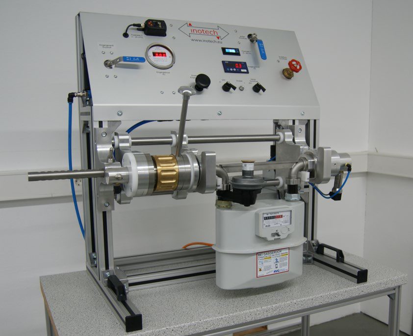
Portable manual rig.
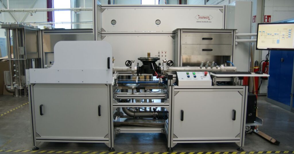
Fully automatic rig.
Choosing a rig: six questions to settle first
One message repeats across all four parts of the training: a rig is specified from the meter outward.
-
1
Which meter technology?
Diaphragm, ultrasonic, microthermal, rotary and turbine meters each need different clamping, pulse pickup and communication.
-
2
What flow range?
From the minimum flow of the smallest meter to the maximum flow of the largest. This sets the size and overlap of the references.
-
3
Which gas, at what pressure?
Air at atmospheric pressure covers most domestic work. Service above 4 bar, natural gas or hydrogen point towards a closed loop.
-
4
How many meters per shift?
Throughput decides the number of positions, the level of automation and the clamping system.
-
5
Can the room hold its conditions?
Temperature stability, conditioning space and utilities are part of the investment, not an afterthought.
-
6
Who keeps the reference traceable?
Plan recalibration intervals, drift monitoring and the accredited chain behind the reference from day one.
Terms and G-ratings
Meter under test (MUT)
The meter being calibrated or verified against the reference.
Base conditions
The agreed pressure and temperature to which measured volumes are converted for comparison.
Choked or critical flow
Sonic velocity at the nozzle throat, held as long as the pressure ratio across the nozzle is sufficient.
Plenum
A low-velocity chamber that provides a steady upstream gas state for the nozzles.
Compressibility factor, Z
Accounts for the departure of a real gas from ideal gas behaviour.
Reynolds number
The balance of inertial and viscous effects in a flow. It governs how a meter responds to a given gas.
Transfer standard
A calibrated reference that carries its calibration and uncertainty into another measurement setup.
Qmin and Qmax
The minimum and maximum flow rates between which a meter must stay within its permitted error.
Reading a G-rating
European meter sizes are given as G-ratings. The maximum flow is roughly 1.6 times the G number, which is why a G25 bench position is specified at 40 m³/h and a G400 revolver at 650 m³/h.
G-rating Qmax, m³/h
- G1.6
- 2.5
- G2.5
- 4
- G4
- 6
- G6
- 10
- G10
- 16
- G16
- 25
- G25
- 40
- G40
- 65
- G65
- 100
- G100
- 160
- G160
- 250
- G250
- 400
- G400
- 650
Sources
Inotech Meter Calibration Systems has developed test rigs since 1992, with sites in Germany and Spain. The company reports more than 1,000 test rigs installed worldwide and a calibration laboratory accredited by DAkkS to DIN EN ISO/IEC 17025 for volume gas flow since March 2021.

About Inotech
Three decades of precision in gas and water meter testing
Inotech was founded in Bietigheim, Germany, in October 1992 by Dipl.-Ing. (BA) Ralf Schneiderat. It has since become one of the established names in meter calibration, trusted by meter manufacturers, calibration laboratories and utilities around the world.
Every Inotech rig is developed, built and tested in-house, under the company motto “Perfection in Precision”.
- 1992
- Founded in Bietigheim, Germany
- 1,000+
- Test rigs installed worldwide
- 70+
- Countries with Inotech systems
- 0.25%
- Uncertainty or better on its high-pressure rigs
Gas meter testingInotech’s core since 1992
- Every scale of meter: benches for domestic, commercial and industrial meters, from production lines to laboratories.
- High-pressure closed loops for air and natural gas, up to 65 bar and 30,000 m³/h, recognised by PTB.
- Laser pulse detection behind what Inotech calls the fastest rotary gas meter test rig in the world.
- Pressure regulator rigs built to DIN 33822, from manual benches to fully automatic lines.
Water meter testingDomestic and industrial meters
- Gravimetric rigs with high-accuracy balances, including flying-start testing.
- Piston provers for DN15 to DN25 meters, with two lines so one tests while the other is loaded.
- Volumetric rigs with calibrated stainless steel tanks, and portable reference meters for field checks.
- Large-meter rigs from DN50 up to DN300, with test procedures to ISO 4064-3 and EN 14154-3.
What sets Inotech apart
- Built in-houseDesign, electronics, software, assembly and testing all happen in Bietigheim.
- High-pressure specialistsA dedicated team works only on closed-loop calibration rigs.
- Accredited laboratoryDAkkS-accredited to DIN EN ISO/IEC 17025 for volume gas flow since 2021.
- Made to lastRigs designed for decades of service, with recalibration and modernisation along the way.
Inotech in Egypt
Inotech is now part of the ZERA Group. Infinity Egypt is your exclusive gateway in Egypt.
Since 1 July 2026, inotech Germany GmbH has been a wholly owned subsidiary of ZERA GmbH. As ZERA’s exclusive partner in Egypt, Infinity Egypt is your single point of contact for Inotech gas and water meter testing in the Egyptian market.
- 1 July 2026
- inotech Germany GmbH joins the ZERA Group as a wholly owned subsidiary.
- Bietigheim
- Inotech’s site in Germany, its team and its know-how continue as before.
- 70+ countries
- ZERA works through partners worldwide. In Egypt, that partner is Infinity Egypt.
One partner for electricity, gas and water meter testing
-
Electricity metersZERA
Stationary and portable meter test systems, already supplied in Egypt by Infinity Egypt.
-
Gas metersInotech
Domestic meter benches, industrial rigs, high-pressure closed loops and pressure regulator rigs.
-
Water metersInotech
Gravimetric and volumetric test rigs for domestic and industrial water meters.
Planning a gas or water meter test facility?
Utilities, meter manufacturers and calibration laboratories in Egypt can reach Inotech through one local team.
- Share your requirementsThe meters you test, the flow range you need and where the rig will stand.
- We define the solution with InotechThe right rig for your meters, your throughput and your laboratory.
- One contact in EgyptInfinity Egypt stays your point of contact through the project.