- phases 1
- Accuracy class 0.02
- Output power U 1x 1500 VA
- Voltage generation max. 480V (AC)
- Output power I 1x 2800 VA
- Power generation max. 120 A (AC)
- Fully electronic test voltage and current generation.
- Built-in reference standard meter directly connected to the test circuit.
- PC-controlled system with real-time display of: Test voltage & current Meter errors
- Individual error display at each test position.
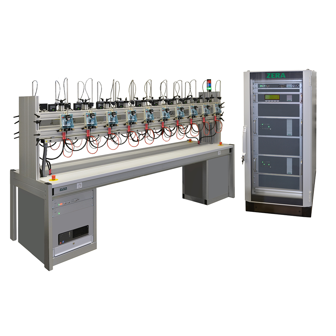
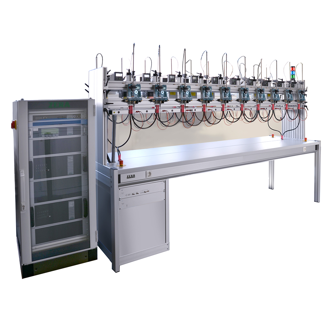
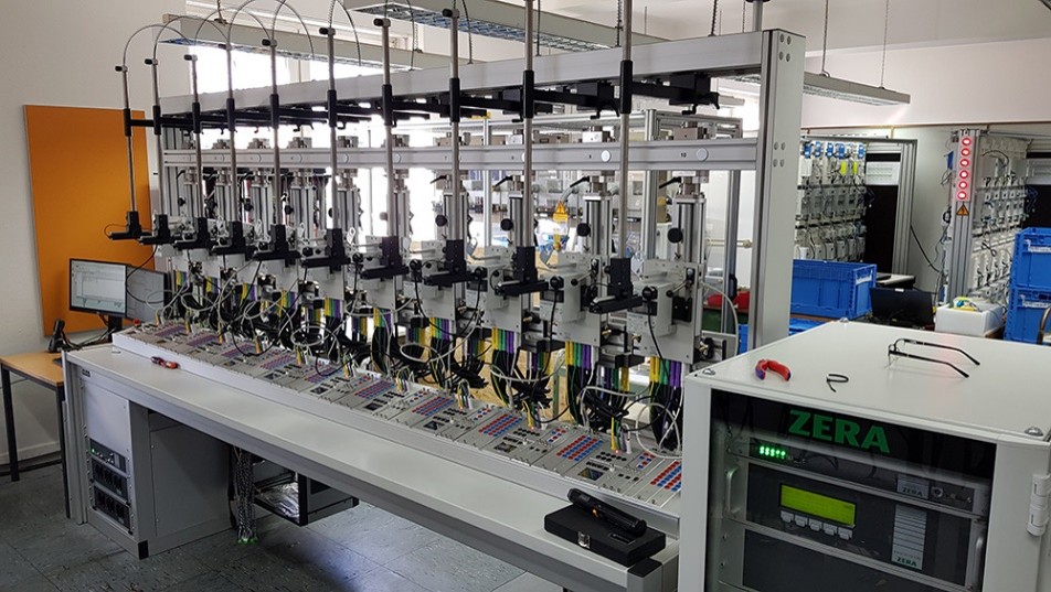
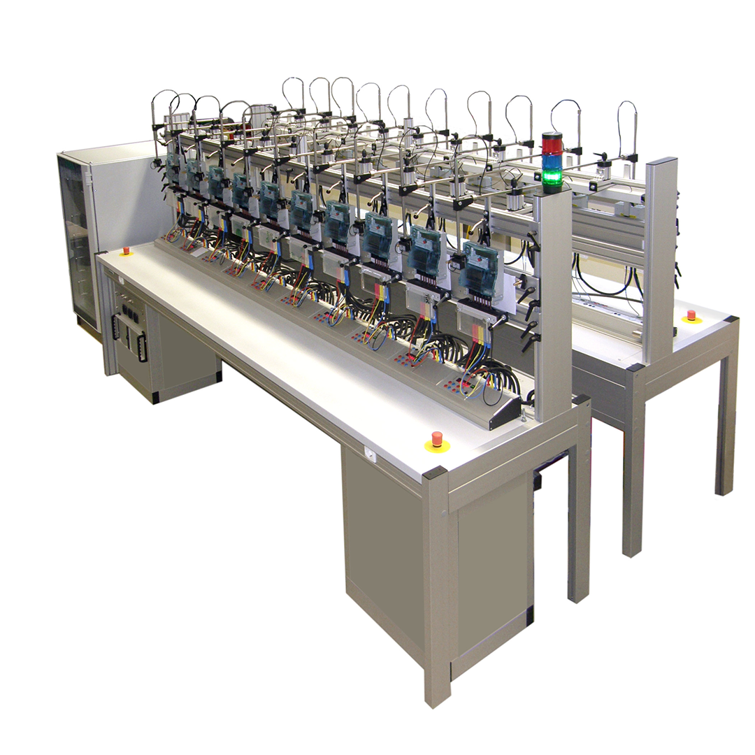
- Double-sided test table (10 meters per side).
- Total capacity: 20 meters simultaneously.
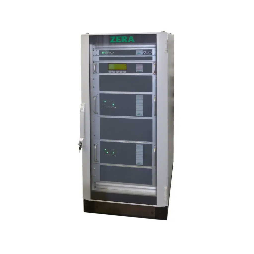
- EPZ303, reference meter
- FG301, frequency generator
- VI202, current amplifier
- VU221, voltage amplifier
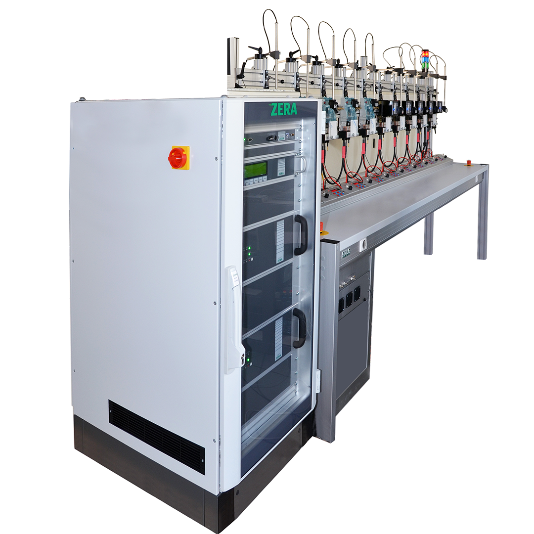
- switch cabinet
- Fan unit with control
- main switch
- Use in stationary ZERA meter testing equipment
- Pre-warming.
- Accuracy testing of energy meters.
- Starting Current Test.
- Creep Test.
- Influence quantity test as per IEC 62053-11,21, 22,23,24, EN 50470-1:2006, EN 50470-3:2006 (which are mainly linked with accuracy test).
- Dial test/Register test.
- Influence of self-heating.
- Influence of heating test ” Additional calibrated thermometer is required from local market (provided by the customer) to perform this test”.
- Harmonics generations (Harmonics up to 2nd to 21th for voltage amplifier and up to 2nd to 40th for current amplifier)
- Sub-Harmonics and even/ odd Harmonics generation.
- Influence of supply voltage: “Voltage interruption /voltage dips / severe voltage variation” test.
- Absolute measurement or Testing of reference meter Immunity of earth fault.
- No load condition test.
- Meter constant test.
- Absolute measurement or testing reference meter up to class 0.05.
- Direct connection to unstabilized mains: 3 × 220/400 V +10–15%, 50 Hz ±2% Adaptable to other voltages or 60 Hz systems upon request
ZERA STATIONARY METER TEST SYSTEM
Smart meters are advanced digital devices that do far more than measure energy consumption. They accurately record electrical parameters, securely communicate with utility systems, support remote operations, and provide real-time visibility across the distribution network.
By combining metrology, communication, cybersecurity, and control capabilities, smart meters enable utilities to deliver efficient, reliable, and data-driven energy services.
MARKET-LEADING ACCURACY
Available in highly precise accuracy classes of 0.005%, 0.008%, and 0.02%.
SUSTAINED STABILITY & ACCURACY
Features multi-wound core Isolated Current Transformers (ICTs) engineered for long-term reliability and accuracy.
TAMPER SIMULATION
Fully capable of simulating a wide variety of electrical tamper conditions.
COMPREHENSIVE SMART METER VALIDATION
Provides End-to-End testing, interoperability, and interchangeability validation for smart metering systems.
COMMUNICATION ADAPTABILITY
Ready-made to adapt to multiple communication technologies, including wireless systems (GSM,GPRS,RF, Bluetooth etc.)
FUNCTIONAL FIELD SIMULATION
Enables simultaneous testing of connected smart meters under simulated field boundary conditions, verifying functionality like sustained accuracy during active communication.
UNIVERSAL QUICK ACTING CONNECTION DESIGN
provide flexibility to quickly connect all type and size of emery meter on test system
ERROR ELIMINATION
Allows direct testing of CT/PT meters without requiring ICTs, successfully eliminating additional error due to ICTs.
EXTENDED FACILITY FOR SMART TESTING
MULTIPLE POSITION
VTT – Validation Test Tool -
Boundary Condition simulation - E2E Communication Test - Interoperability Test - Variation of Accuracy During communication - Negative Tests.
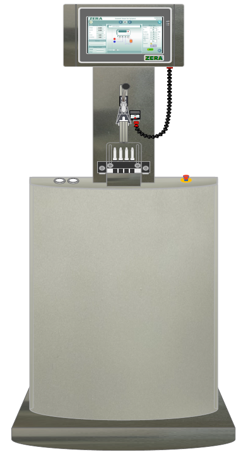
TAMPER SIMULATOR
Tamper defined by CBIP -
Legitimate time event reporting -
Actual Load conditions -
Checking Communication -
End to Verification.
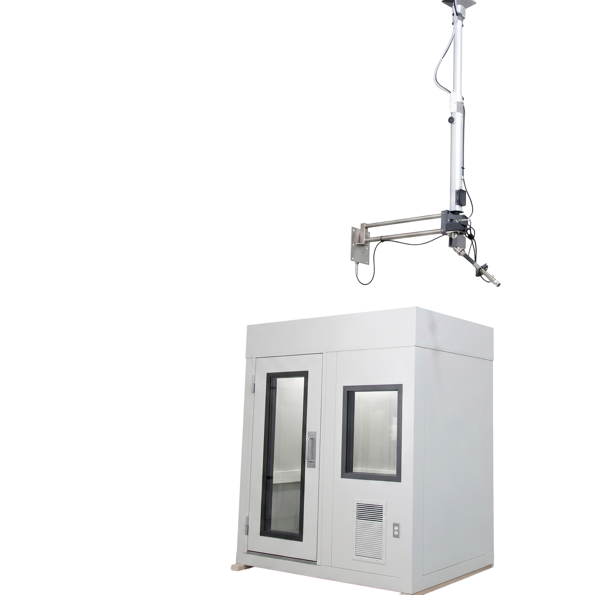
RF HINDRANCE
Legitimate time event reporting -
Load Switch behavior -
FOTA and Retry -
Cross Verification Display+ HES .
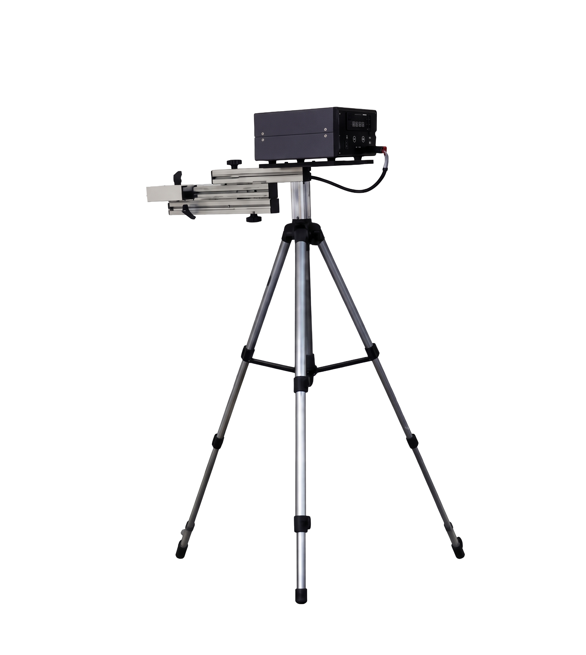
Magnetic Immunity Testing
DC Solenoid Test - Simulates continuous DC magnetic fields - Verifies meter resistance against magnetic tampering - Evaluates measurement accuracy under magnetic influence - Confirms compliance with IEC magnetic immunity requirements.
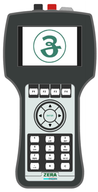
COMMUNICATION BURDEN
BURDEN MEASUREMENT: Idle Mode - Active Transmission - IHD Module - Power Consumption Analysis - Measures communication module power consumption - Evaluates burden during Idle and Active modes - Verifies IHD communication load - Optimizes meter energy efficiency.
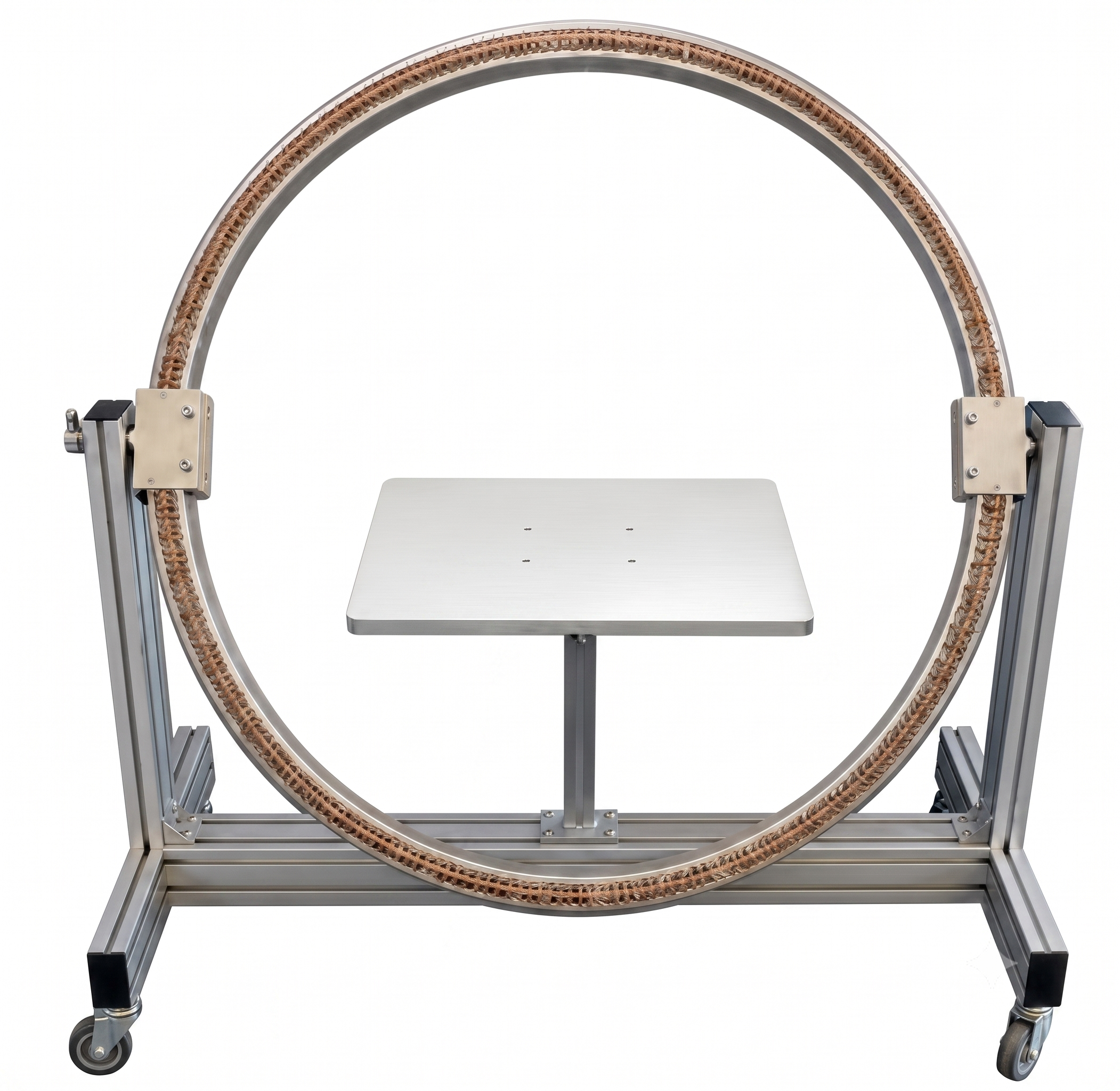
EXTERNAL FIELD COIL
MAGNETIC FIELD TEST: 0.5 mT Magnetic Field - 50 Hz AC Field - Uniform Field Generation - Repeatable Test Conditions - Generates a controlled 0.5 mT magnetic field - Verifies immunity against external AC magnetic fields.