
Testing the Meters That Bill the Nation

Water Meter Calibration with inotech.

How water and heat meter test benches are built, traced back to the kilogram and chosen for the job. 

By Lena Elsayed, Brand Manager
October 1, 2026
20 minutes read

Why the bench matters

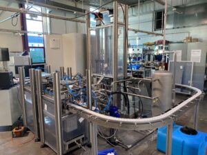
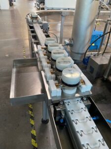
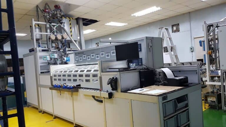
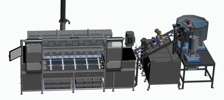
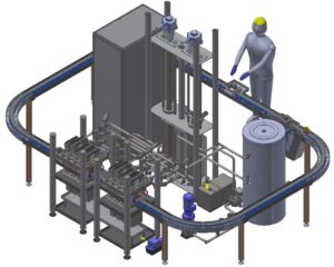
test bench for industrial water meter testing
A water meter is allowed to be wrong, but only by a fixed amount. The test bench is how anyone proves it stays inside that limit. Under ISO 4064-1:2024 and its twin, OIML R 49-1:2024, an accuracy class 2 meter may read up to ±2 % off in its upper flow zone and ±5 % at its lowest flows. A class 1 meter is held to ±1 % and ±3 %. Every bill a utility sends, and every non-revenue water figure it reports, assumes its meters stay inside those limits. A bench checks this by passing a known quantity of water through the meter and comparing it with what the meter indicates. That known quantity must be far more certain than the meter itself. OIML R 49-2 caps the expanded uncertainty of the reference volume at one-fifth of the meter's maximum permissible error (MPE) for type evaluation and one-third for initial verification.
Maximum bench uncertainty by meter accuracy class
Meter, upper flow zone MPE Bench limit, type evaluation (⅕ MPE) Bench limit, initial verification (⅓ MPE)
Accuracy class 1 ±1 % 0.20 % 0.33 %
Accuracy class 2 ±2 % 0.40 % 0.67 %

Bench limits follow OIML R 49-2: the expanded uncertainty of the reference volume may be at most one-fifth of the meter's MPE for type evaluation and one-third for initial verification.

Germany’s verification rules go further. GM-P 5.22 requires a cold-water rig to reach a combined standard uncertainty of 0.10 % or better across its whole flow range. At a coverage factor of k = 2 that is about 0.2 % expanded, which is what a class 1 meter’s type evaluation demands.

The rest of this article explains how benches reach those numbers: the reference methods, the hardware inside a gravimetric rig, the piston systems built for production speed, and the practical lessons inotech’s engineers shared in a recent training session for test engineers.

inotech builds calibration systems for meters, and nothing else. Its benches calibrate millions of gas, water and heat meters every year. Since joining the ZERA Group in 2026 it also covers electricity meters, so the group now serves all four metered utilities.

    • Two production sites. Bietigheim in Germany, which also houses the laboratory, and Montornès del Vallès near Barcelona, Spain.
    • Water and heat know-how from Spain. The Spanish site joined on 1 July 2021. In the training session inotech explained that it grew from a former Itron team with a long history in water and heat meter calibration. Most of the water benches in this article were built there.
    • Accredited laboratory. Since March 2021 the lab has held DAkkS accreditation (D-K-23505-01) to ISO/IEC 17025:2018 for the measurands of gas meter test systems: pressure, temperature, relative humidity, time and gas volume flow. It also supports water and heat customers with pressure, temperature and external scale calibration.
    • Long service life. inotech guarantees spare parts for ten years and modernises existing benches, including those from other manufacturers.

Gravimetric

Reference: mass

Water that has passed the meters is collected and weighed. Volume follows from the water's density at the measured temperature.

Strength
Traces directly to the kilogram with the lowest uncertainty. It is also used to calibrate the standards the other methods rely on.
Watch for
Weighing, settling and draining are part of every test cycle.
Typical home
Verification bodies, reference and accredited laboratories.

Piston and double piston

Reference: displaced volume

A precision piston on an electric linear drive pushes a calibrated volume of water through the meters.

Strength
Flow is set by drive speed, so the bench settles in 1 to 3 seconds. The highest throughput of any method.
Watch for
The cylinder volume must itself be traced, by weighing or against a calibrated volume.
Typical home
Meter manufacturers' production lines.

Volumetric

Reference: vessel volume

Water collects in a calibrated standard measuring vessel and its level is read off a scale.

Strength
Simple and robust.
Watch for
Scale reading, meniscus, wetting and residual water dominate the uncertainty. GM-P 5.22 admits it only on cold-water rigs, and it is less common today.
Typical home
Simple cold-water rigs.

Master meter

Reference: meter pulses

A calibrated reference meter in series with the meters under test supplies the reference value.

Strength
Fast and easy to automate, and practical at high flow rates.
Watch for
Every result inherits the reference meter's uncertainty, drift and recalibration interval.
Typical home
Large meters and high flow rates.

Red outline: methods traced to the kilogram by weighing

Kilogram SI unit of mass Scales + reference weights Gravimetric rig weighs every test Piston cylinder weighed once, in 2 l segments Master meters reference: pulses Standard vessels reference: volume then tests at drive speed, with no weighing in the cycle Kilogram SI unit of mass Scales + reference weights Gravimetric rig weighs every test Piston cylinder weighed once, in 2 l segments Master meters reference: pulses Standard vessels reference: volume then tests at drive speed, with no weighing in the cycle

Four methods, one root. Both highlighted methods are gravimetric at heart: a piston system does not replace weighing, it moves the weighing out of the test cycle and into the calibration of the cylinder.

Inside a gravimetric rig

A gravimetric rig is a closed water loop with a scale at the end of it. Water circulates from a storage tank, passes the meters under test, and is caught in a weigh tank for a precisely timed interval.

 
THE REFERENCE weighed mass Storage tank vented, temperature-stabilised Pump variable speed METERS UNDER TEST, IN SERIES · 1 × 1 UP TO 2 × 15 MUT 1 MUT 2 ··· MUT n MID 1 high flow MID 2 medium flow MID 3 low flow CV 1 CV 2 CV 3 Diverter 1 Weigh tank 1 Scale 1 · high range Diverter 2 Weigh tank 2 Scale 2 · low range bypass drain bypass drain Return line · closed loop measuring path return, bypass, drain THE REFERENCE · WEIGHED MASS Storage tank vented, temperature-stabilised Pump variable speed METERS UNDER TEST, IN SERIES · UP TO 2 × 15 MUT 1 MUT 2 ··· MUT n MID 1 + valve CV 1 high flow MID 2 + valve CV 2 medium flow MID 3 + valve CV 3 low flow Diverter 2 Weigh tank 2 Scale 2 · low range Diverter 1 Weigh tank 1 Scale 1 · high range measuring path return, bypass, drain

Basic components of a gravimetric rig, after inotech's schematic. The test line can carry one meter or up to two lines of fifteen. Control valves (CV) sit downstream of the meters; the diverters and scales are the reference of the whole rig.

Main components of a gravimetric rig and their function
Component Job in the rig Typical build
Storage tank Holds the circulating water, decouples the pump from the weighing side, lets air and temperature settle Stainless steel, vented, temperature-stabilised
Pump(s) Generate flow and the pressure needed across meters, valves and pipework Centrifugal pump with variable-frequency drive; flow straightener downstream
Test line Carries the meters in series with defined inlet and outlet straight lengths Clamping device; one common flow through all meters
3 × MID Measure the actual flow, feed the control loop, and can serve as secondary references Electromagnetic flow sensors in staggered nominal sizes
3 × control valve Set the test flow rate and hold it constant during collection Motorised valves, one per branch, downstream of the meters
2 × diverter Start and end the collected quantity without interrupting the flow Symmetrical two-way diverter, switching time ≤ 0.5 s
2 × weighing system Determine the collected mass: the reference quantity of the whole rig Weigh tank on a scale of accuracy class III or better, two capacities

Three flow branches, one continuous range

Between Q1 and Q4 a water meter typically spans a range of 1 : 100 to 1 : 400. A single flow sensor stretched across that span would work far from its optimum at the low end, where its own uncertainty would dominate the test. The rig therefore splits the range across three parallel branches, each with its own MID and control valve, in sizes staggered to match. GM-P 5.22 explicitly allows parallel flow-setting and measuring devices of different sizes in the outlet line behind the meter (4.2.2).


The control valves sit downstream of the meters on purpose. The back pressure they create prevents cavitation and the release of dissolved air at the meters under test. A closed control loop on the MID signal then holds the flow steady: GM-P 5.22 asks for no more than ±2.5 % change from Q1 to Q2 and ±5.0 % from Q2 to Q4 during a test (4.2.9).

Two scales, two diverters and a flying start

Each weighing system combines a diverter, a weigh tank and a scale. The large system serves high flow rates, where the required volume builds up quickly and the collected mass stays large compared with the scale’s resolution. The small system, with fine resolution, serves Q1 and Q2. Without it, the mass collected at minimum flow would be so small that the resolution and repeatability of a large scale would govern the result.


Because the flow is never interrupted, everything depends on how cleanly the diverter switches. GM-P 5.22 requires it to switch symmetrically, equally fast in both directions, in 0.5 s or less, with the whole stream ending up either in the weigh tank or outside it (4.2.5.2). Its share of the uncertainty budget is capped at 0.06 % on cold-water rigs, which counts as met if the volume deviations found when testing the diverter stay within ±0.1 %.


Two rule books, one rule of thumb

GM-P 5.22 asks for a total test time of at least 50 times the switching time when meters are read visually. OIML R 49-2 reaches the same ratio from the other side: the diverter's contribution is negligible if its two movement times agree within 5 % and each takes less than 1/50 of the test time. A 0.5 s diverter therefore needs tests of 25 s or longer.
01

Evacuate, fill, condition

After the meters are changed, air is evacuated, the loop is filled and circulated, entrained air is vented and the temperature settles. No air may reach the test line during a test (4.2.10).

02

Select branch and setpoint

The test point (Q1, Q2 or Q3) decides which MID and valve branch and which weighing system are used.

03

Stabilise

The control loop drives the valve to the setpoint. Collection starts only once flow, temperature and pressure are steady.

04

Start collection

The diverter swings from bypass to weigh tank. The meters' indications are captured at that instant.

05

Stop collection

After the set collection time the diverter swings back, and the second reading is captured at that transition.

06

Weigh and evaluate

After a waiting time the scale value is converted to volume and compared with each meter. The tank drains back to storage.

Steps 2 to 6 repeat for every test point. With automatic pickup of the readings, the test volume is set so that ten consecutive measurements stay within the required repeatability.

Meters can be tested in series, and GM-P 5.22 expressly permits it, provided there is proof that the meters do not influence each other and that the pressure at the end of the line rules out cavitation (4.2.1). OIML R 49-2 sets a practical floor: at least 0.03 MPa (0.3 bar) gauge pressure at each meter outlet.

From mass to volume

The scale delivers a mass, while the meter indicates a volume. GM-P 5.22 (section 6.2.3.2) links the two through the density of the water at its measured temperature and a correction for air buoyancy.

 
VN = Wρw(ϑw) × KLA
f = VP − VNVN × 100 %
VN delivered volume, the reference value VP volume indicated by the meter under test; f is its relative error W weighing value, the difference between the two scale readings ρw(ϑw) water density at the water temperature in the meter, measured in the test line before or after the meter KLA air-buoyancy factor, (1 − ρL/ρG) / (1 − ρL/ρw), with ρL the air density and ρG = 8,000 kg/m³ the density of the scale's reference weights

With the approximations in 6.2.3.2, KLA may be taken as the constant 1.0010: air buoyancy adds about 0.1 % to the weighed result, which is the same size as the rig’s whole uncertainty budget. The water density is taken as that of distilled water at the measured temperature plus a constant correction for the actual water, checked to within 0.3 kg/m³, for example after every water change.

Piston and double piston: weigh once, test fast

A piston bench does its weighing once, in advance, so that every test afterwards runs at the speed of an electric drive. That is why meter manufacturers, where calibrations per shift decide the economics, prefer it.

 
flow rate is set by drive speed, not by pump and valve

Single measuring piston: one cylinder, one linear drive. The drive pushes the piston through a defined stroke, and the volume it displaces is the reference.

Because flow is set by the speed of the drive, it is constant by construction. The training session put a number on the benefit: the bench settles in 1 to 3 seconds, against the minutes a pump-and-valve loop can need at low flow. Add automated loading and unloading of the meters and the bench becomes a production station.

How the cylinder is traced to the kilogram

Weighing segment by segment maps the volume actually displaced along the stroke, rather than one averaged figure. A deviation in the bore or the seal position shows up exactly where it occurs. A high-quality calibrated volume standard, or direct measurement of the piston geometry, are the alternative routes. Either way the reference quantity is still mass: the weighing has simply been done once, on the cylinder, instead of on every test.

Double measuring piston: the fastest arrangement

The double piston places the meters under test between two cylinders, each with its own drive. A valve block reverses the direction after every test: cylinder A delivers through the active meter group into cylinder B, and the next test runs the other way round.

 
Linear drive A Cylinder A Valve block GROUP 1 · UNDER TEST MUT MUT MUT GROUP 2 · BEING EXCHANGED MUT MUT MUT Valve block Cylinder B Linear drive B next test: valve blocks reverse, cylinder B delivers into cylinder A Linear drive A Cylinder A Valve block GROUP 1 UNDER TEST MUT MUT MUT GROUP 2 BEING EXCHANGED MUT MUT MUT Valve block Cylinder B Linear drive B next test: valve blocks reverse, cylinder B delivers into cylinder A

Double measuring piston with two groups of three to five meters. The maximum inlet pressure at the meters is 6 bar.

Pressure without a pump

Driving the two pistons against each other pressurises the test line, so meters are tested close to the pressure they see in service.

No changeover time

While one group runs against the pistons, the other is exchanged automatically. Loading and unloading no longer count towards the cycle.

No refill stroke

The cylinder that received water in one test is already full for the next. Reversing the valve block starts the next test straight away.

inotech Germany’s double-piston line calibrates warm water meters at 50 °C. The meter under test sits between two vertical pistons of 6 litres each, covering 4 l/h to a maximum of 6 m³/h, and the line carries meters on trays around a conveyor loop. Its throughput is about 200 meters per hour.


Reading the meter automatically

A fast reference is wasted if a person still has to read every register. How the meter’s indication reaches the bench software decides much of the real throughput.

inotech’s benches read meters three ways: optical scanning of mechanical registers, pulse outputs, and communication protocols, through which smart meters are both read and parameterised over their serial interfaces.

For heat meters, the industry once tried to standardise bench communication through a common protocol called NOWA. It never gained broad support from meter manufacturers, and nobody maintained it, so it never became the standard it was meant to be.

inotech took a different route and builds each manufacturer’s own protocol into its test software. About 12 protocols are integrated today, which is why its heat meter benches are marked “No NOWA required” and can run fully automated tests.

The 2024 edition of ISO 4064 | OIML R 49 makes readout part of the meter’s own design. Three clauses matter to anyone planning a bench:

    • Test mode (4064-1, 5.1.6). Electronic meters may switch to a test mode with a finer display resolution, a shorter sampling interval and an active pulse or digital output to the laboratory’s data acquisition. The manufacturer must supply the equipment or procedure to start it.
    • Sampling interval (5.1.5). In service, an electronic meter may sample at most every 10 seconds.
    • Resolution (6.7.3.2.3). The display’s resolution error may not exceed 0.25 % (class 1) or 0.5 % (class 2) of the volume that passes in 90 minutes at Q1. That rule sets how long a visually read low-flow test must run.

In practice: settle the readout before the bench. Ask meter suppliers early for their test-mode procedure and protocol documentation, because inotech can integrate a protocol once the manufacturer discloses it.

Heat meters: flow and temperature on one bench

A heat meter is three instruments in one: a flow sensor, a pair of temperature sensors and a calculator. Testing it needs a flow reference and a temperature reference at the same time.

 
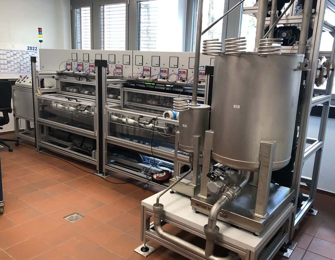
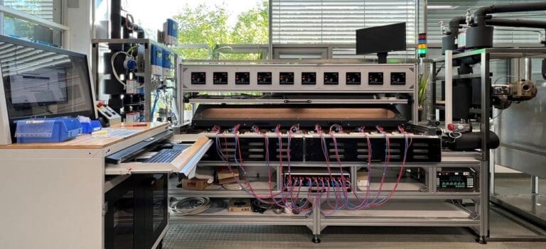
Heat meter test bench with two meter lines, display panels and a stainless-steel weigh tank on a Mettler Toledo scale in the foreground.
Gravimetric heat meter test system, 2022: two lines with up to ten test locations each.
Flow6 l/h – 30 m³/h
Watertypically 50 °C ± 5 °C
ReferencesKrohne MID, Mettler Toledo scales
Positions2 lines × up to 10

Every test station has an integrated temperature-simulation box, and the system is approved by the calibration authorities under current regulations. Manufacturers' protocols are built directly into the software, so results flow into custom test protocols without manual entry.
The most difficult point is the smallest flow, around 6 l/h. A measurement takes a long time there, and the water travels slowly from the meter to the small weigh tank. On that journey it must lose less than 1 °C, or the meter and the reference no longer see the same water.

inotech solves this with additional pre-heating: trace heating along the test line keeps the temperature stable between the meter and the reference, even at minimum flow.

Temperature-sensor simulation

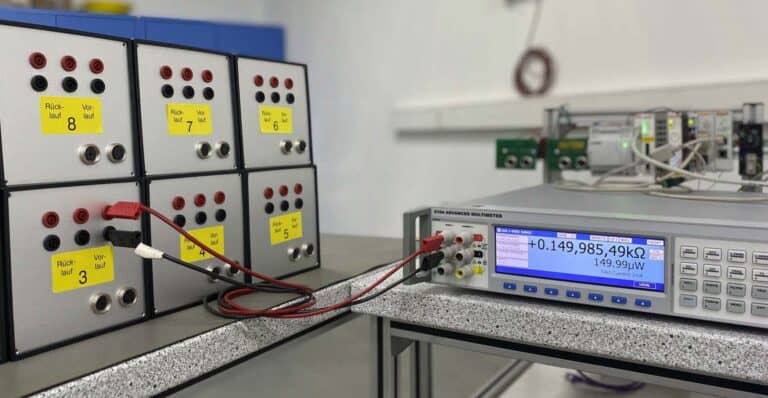
temperature sensor simulation
Temperature-simulation boxes for flow (Vorlauf) and return (Rücklauf) channels, checked against a precision multimeter.

Changing real water temperatures for every test point is slow. Simulation removes that wait. The meter’s temperature sensors are demounted and the simulator is wired straight to the calculator’s inputs. Precision resistors stand in for PT100, PT500 or PT1000 sensors at the flow and return channels, and the software steps through different temperature differences in quick succession.

  • Checks the calculator directly. Each simulated temperature difference tests whether the calculator turns flow and temperature into energy correctly.
  • Semi- or fully automated. The calibration procedure runs with little operator input and stays stable over the long term.
  • Two form factors. Mobile units and boxes integrated into each test station, with a flexible resistor configuration.
  • Compact meters too. Where sensors cannot be removed, inotech uses dry-block calibrators to bring them to the target temperature.

Heat meter benches are designed to EN 1434 and the MID, with Germany’s GM-P 7.2 for heat meter test systems.

Pressure testing: keep it off the metrology bench

Some buyers ask for pressure testing to be built into the calibration bench. inotech’s engineers advise against it, and the reasons are worth knowing before you write a specification.

The requests usually ask for 16 to 32 bar, and those figures come straight from the standard. ISO 4064-1:2024 requires a meter to withstand 1.6 times its maximum admissible pressure (MAP) for 15 minutes and twice its MAP for 1 minute (4.2.10); initial verification applies 1.6 times MAP for 1 minute (7.3.2). With MAP at least 10 bar, a standard meter is tested at 16 bar, and a 16 bar meter’s type test at twice MAP reaches 32 bar.

A meter that fails at 16 to 32 bar can throw out parts with enough force to injure an operator, so any bench that does it needs closed cabinets or protective barriers.

High pressure also stresses the parts a metrology bench depends on for precision: inlet and outlet valves, seals and the test rig itself. inotech recommends running pressure tests on separate, simpler and more robust equipment built only for that job.

Where a customer requires both in one machine, inotech has built them with two safety concepts. Both benches below cover 6 l/h to 20 m³/h with Mettler Toledo scales, and a piston bench with an integrated pressure test (2 l/h – 7 m³/h, 30 l piston, 2019) follows the same idea.


Benches in service

inotech’s water and heat benches cover more than five decades of flow, from 2 l/h on capsule meters to 800 m³/h on DN200 industrial lines. Each one is built around the reference method that suits its range.

Pistons own the small-meter range; weighing and reference meters take over above 54 m³/h

Flow range of each installed bench, logarithmic scale

Piston and double piston Combined piston + scales Gravimetric Reference meter

Source: inotech, Test Benches for Water and Heat Meters, September 2026. Hover a bar for its exact range.
Piston benches
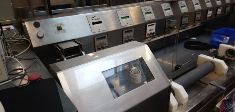
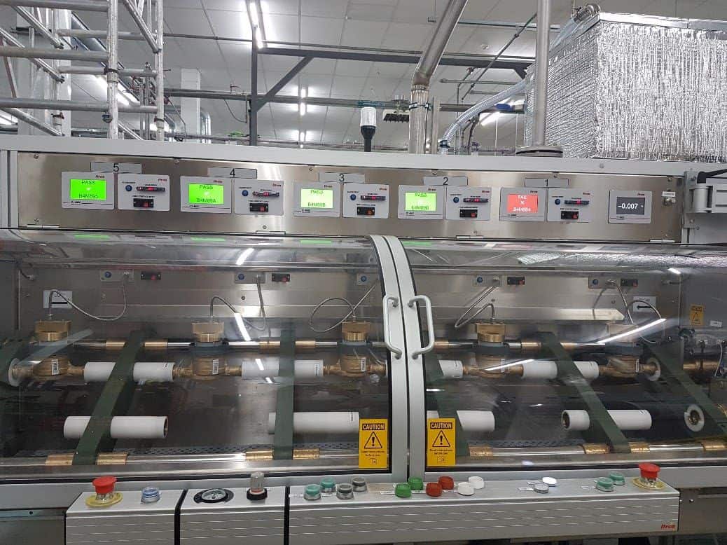
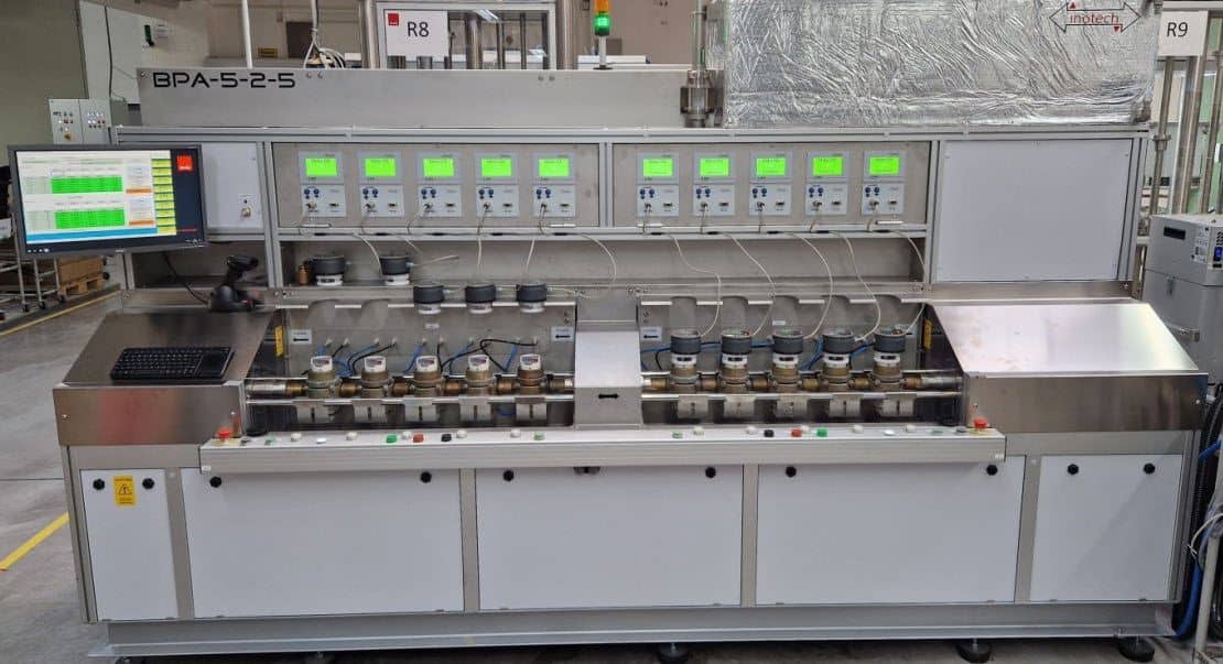
A BPA piston test bench with a row of green displays above a line of clamped water meters behind a clear cover.
Piston · inotech Spain · in production since 2001

BPA series: BPA5, 7, 12 and 50

Flowfrom 3 l/h to a maximum of 5, 7, 12 or 54 m³/h SizesDN15 – DN50 Referencepiston, 30 l to 300 l Builtmore than 65 units

In service with meter makers and utilities on four continents:
Al Maasara, EgyptSMCV Casablanca, MoroccoAlgeriaItron: India, Jakarta, Macon, Germany, MexicoHoneywell, UKBürkert, FranceOTK, JapanMeterTek, MalaysiaJabil, ChinaLAO, BrazilManas, TurkeyIndaqua, PortugalAIOTMGKaha
Capsule water meter test bench with two groups of five clamped meters and green displays above.
Piston · inotech Spain · 2022

Capsule water meters

Flow2 l/h – 7 m³/hReference30 l pistonPositions2 × 5, alternating

Pneumatic clamping holds the capsule meters. One group of five is tested while the other is exchanged, so changeover time drops out of the cycle.
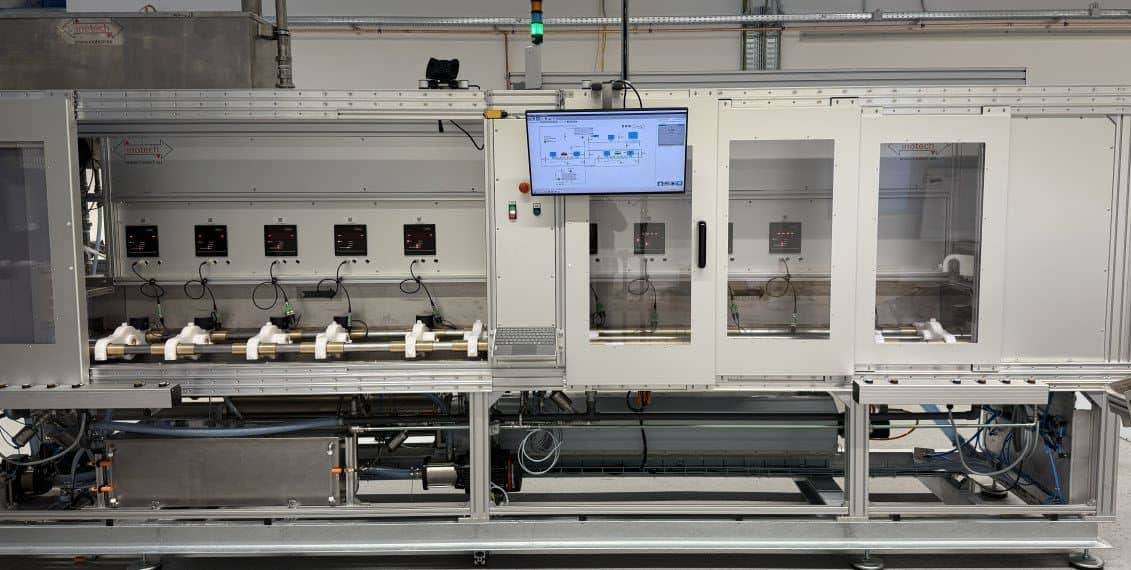
Enclosed domestic water meter test bench with glass doors, a control screen and five meters on the test line.
Piston · inotech Germany · 2025

Domestic water meters

Flow2 l/h – 5 m³/hReference25 l pistonPositions2 × 5, alternating

inotech's newest piston bench, built on the same alternating principle for continuous production.
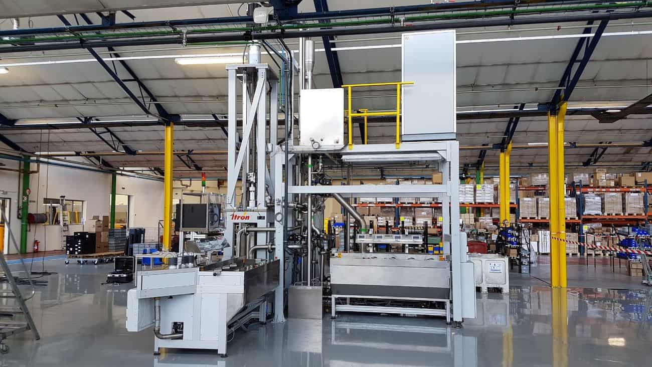
Tall vertical-piston test bench in a large production hall with a platform and yellow railings.
Vertical piston · inotech Spain · 2016–2017

BPA25-2-4-H, warm water at 50 °C

Flow15 l/h – 25 m³/hSizesDN25 – DN50Reference113 l vertical piston

Three units built. Copper heating coils on the test line hold the water at temperature.
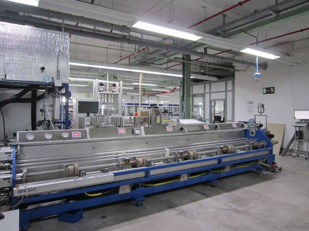
Long horizontal piston test bench with a blue frame and a row of meters along its length.
Horizontal piston · inotech Spain · November 2001

BPA50, still in service

Flow23 l/h – 54 m³/h (50 nominal)SizesDN25 – DN50Reference350 l piston, 300 l effective

A warm-water bench at 50 °C that has worked for a quarter of a century.
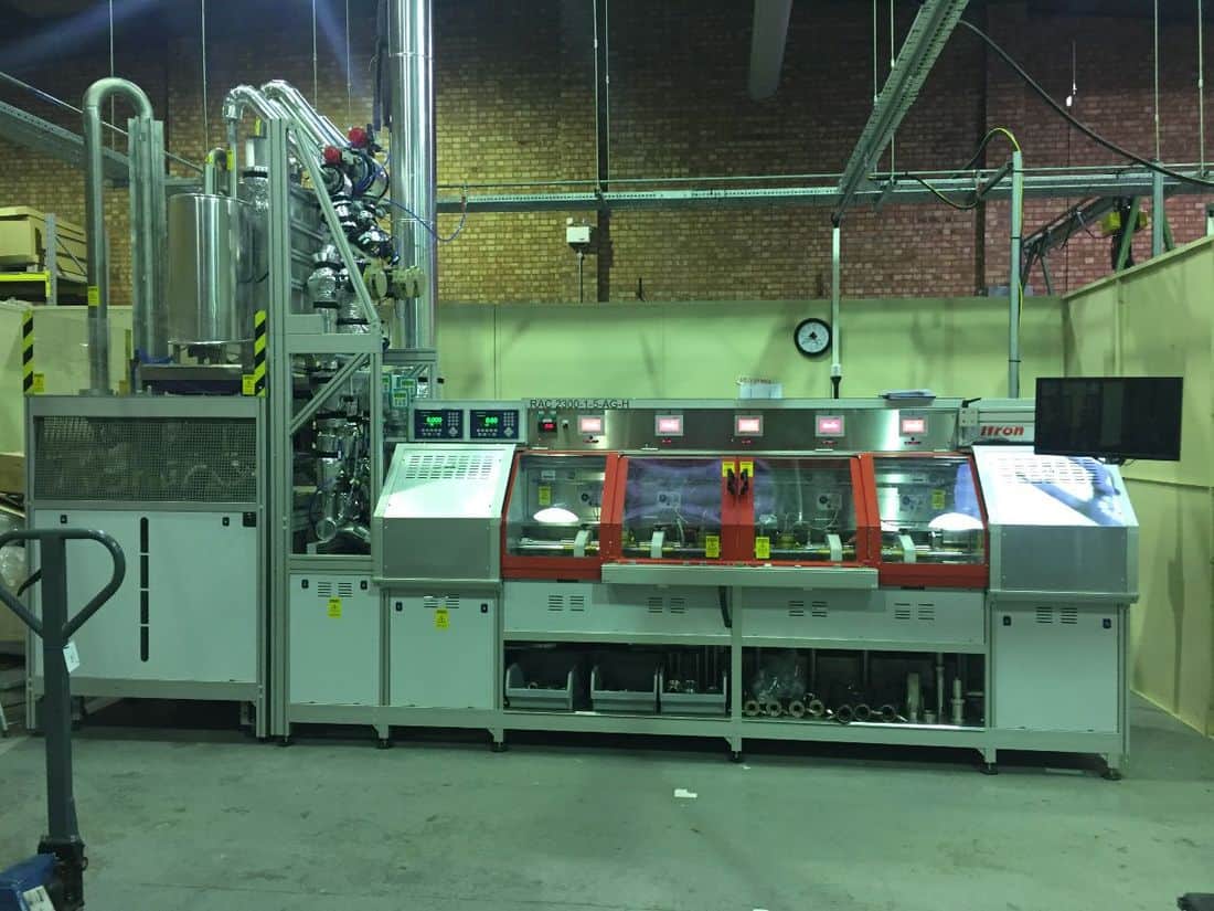
Gravimetric benches
Hot-water meter test bench with red-framed sliding doors over the meter line.
Gravimetric · inotech Spain · 2018 and 2019

Hot-water meters

Flow6 l/h – 25 m³/hWater5 °C to 90 °CReferencesSiemens MID, Mettler Toledo scales

Sliding doors and shutters shield operators from hot water; one version can be fully enclosed.
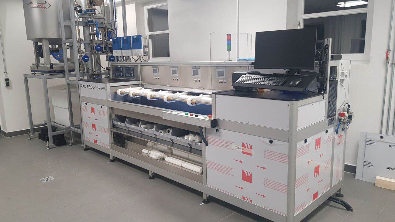
Statistical-testing bench with a weigh tank on a scale at left and four meters clamped on the test line.
Gravimetric · inotech Spain · 2021

Statistical testing, cold water

Flow2 l/h – 20 m³/hPositions4 meters per testReferencesKrohne MID, Mettler Toledo scale

Two identical benches built for sampling limited batches, such as incoming meter lots.
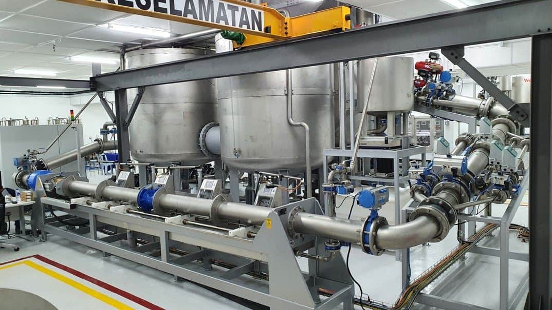
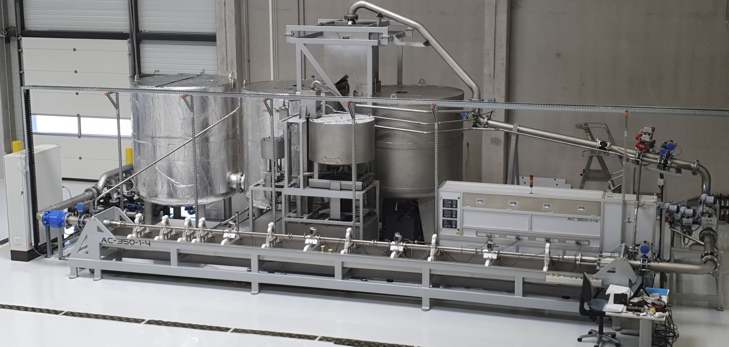
Industrial water meter test bench with two large tanks, wide stainless pipework and blue flanged valves.
Gravimetric · inotech Spain · 2021

Industrial meters up to DN200

Flow60 l/h – 800 m³/hPositionsup to 2 meters, DN200ReferencesSiemens MID, Mettler Toledo scales

The widest range in the portfolio, with pumps and control cabinets behind the line.
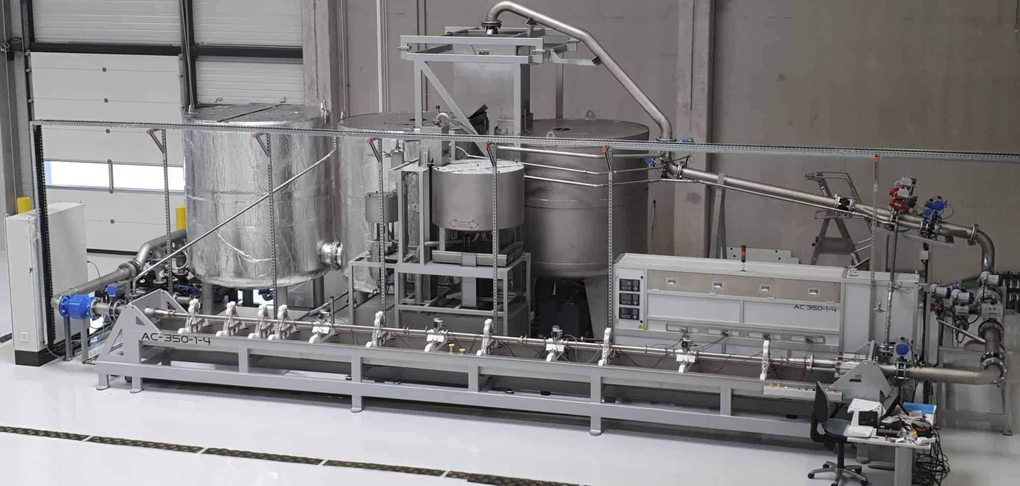
Gravimetric bench with a very long meter line for surface acoustic wave meters.
Gravimetric · inotech Spain · 2023

Long line for SAW meters

Flow500 l/h – 350 m³/hLinevery long meter-under-test lineReferencesKrohne MID, Mettler Toledo scales

Built for surface acoustic wave meters, with very low uncertainty.
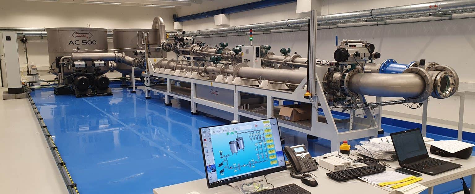
Reference meter and combined benches
Industrial reference-meter bench with large pipes and electromagnetic flow meters over a blue floor, with an operator screen showing the plant schematic.
Reference meter · inotech Spain · 2024

Industrial meters, no weighing in the cycle

Flow5 – 500 m³/hReferences2 × 3 Yokogawa MID, Coriolis transfer meters

At large sizes, reference meters keep tests short; the Coriolis transfer meters link them back to a gravimetric calibration.
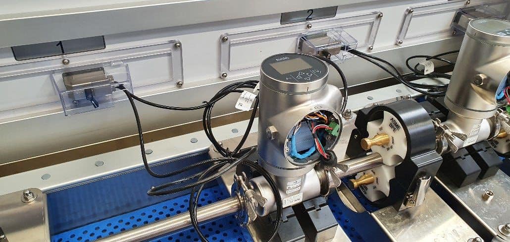
Close-up of the Combical meter line with clamped meters and an electromagnetic flow sensor.
Piston + gravimetric · inotech Spain · July 2020

Combical: one bench, two references

Flow3 l/h – 54 m³/hSizesDN25 – DN50Referencespiston 3 l/h – 2 m³/h; scales and MID 2 – 54 m³/h

Each reference is used where it is strongest: the piston at low flow, weighing at high flow.

Modernising old benches

A bench whose mechanics are sound but whose controls, PC or references have aged can be brought up to date instead of replaced, including benches inotech did not build.


In 2022 inotech Germany rebuilt this heat meter bench. It now covers 6 l/h to 20 m³/h with up to ten meters per test, uses Krohne MID and Mettler Toledo scales as references, and has integrated temperature-simulation boxes and trace heating for stable minimum flows. It passed metrology approval after the upgrade and, like the new heat bench, needs no NOWA.

Retrofits typically renew the control system, PC and test software while keeping the hydraulic frame. With a ten-year spare-parts guarantee and benches from 2001 still in daily use, the life of a well-built rig is measured in decades.

Limits and standards to design for

Two sets of numbers shape every bench: what the meter is allowed to do, and what the rig must achieve to judge it.

Maximum permissible errors for the meter

Maximum permissible errors of water meters by accuracy class and flow zone
Accuracy class Lower zone, Q1 ≤ Q < Q2 Upper zone, 0.1–30 °C Upper zone, above 30 °C
Class 1 ±3 % ±1 % ±2 %
Class 2 ±5 % ±2 % ±3 %
  • Fixed flow ratios. Q2/Q1 = 1.6 and Q4/Q3 = 1.25; Q3/Q1 is chosen from a series between 40 and 1,000.
  • Verification points. Initial verification tests at least Q1, Q2 and Q3; type evaluation adds 0.35 (Q2 + Q3), 0.7 (Q2 + Q3) and Q4.
  • Repeatability. At type evaluation, the standard deviation of three measurements may not exceed one-third of the MPE.
  • Series testing. Meters of the same size and type may be verified in series if each meets its outlet-pressure condition and they do not interact.
  • In service. Annex C suggests twice the MPE for meters already installed.

Source: ISO 4064-1:2024 | OIML R 49-1:2024, clauses 4.1, 4.2, 7.2–7.3 and Annex C.

Requirements on the rig under GM-P 5.22

GM-P 5.22 requirements for cold-water meter test rigs
Subject Requirement for cold-water rigs Section
Rig as a whole Relative combined standard uncertainty of the volume ≤ 0.10 % over the whole load range (hot-water rigs 0.15 %) 4.2.1
Water temperature Must not exceed 30 °C anywhere in the test equipment 4.2.8
Flow constancy ±2.5 % from Q1 to Q2, ±5.0 % from Q2 to Q4; in a closed loop met if pressure-drop fluctuation stays within ±5 % / ±10 % 4.2.9
Diverter Symmetrical, equally fast both ways, switching time ≤ 0.5 s; position indicator recommended; effect checked at several flow rates 4.2.5.2
Scale DIN EN 45501, accuracy class III or better, able to carry the weigh tank 4.3.1
Weigh tank No rigid connections while weighing; no filling from below; dip-tube buoyancy corrected; tank should be covered 4.3.1.2
Intermediate pipe As short as possible; volume not above the minimum test volume; temperature change over a measurement ≤ 1.0 °C 4.2.2
Straight lengths Inlet ≥ 10 × DN, outlet ≥ 2 × DN free of restrictions for axial meters, MID and ultrasonic sensors; flow straightener after centrifugal pumps 4.2.7
Air No air in the test line; pump suction pressure ≥ 0.1 bar, otherwise a gas separator of ≥ 1.5 l per m³/h of the largest flow 4.2.10

Standards inotech builds to

ISO 4064-1 to -5:2024 OIML R 49-1 to -4:2024 MID 2014/32/EU, MI-001 ISO 4185, gravimetric method ISO 8316, volumetric method EN 1434, heat meters DIN EN 45501, scales ISO/IEC 17025:2017 GM-P 5.22, water meter test systems GM-P 7.2, heat meter test systems

GM-P 5.22 and GM-P 7.2 are German verification requirements. They are not law in Egypt, but they are among the most detailed public rule sets for test rigs and make a useful specification baseline anywhere.

Choosing a bench

The right bench follows from the job: traceability points to weighing, throughput points to pistons, and meter size points to industrial lines.

 
Which inotech test bench fits which priority
If your priority is Consider Why
Lowest uncertainty and direct traceability Gravimetric bench, two scales, three MID branches Mass is the reference; the chain ends at the kilogram
High-volume production of domestic meters BPA or alternating 2 × 5 piston bench 1–3 s settling; meter changeover runs outside the cycle
Maximum throughput of warm-water meters Double piston No refill stroke and no changeover time; about 200 meters per hour
One bench for DN25–DN50 across the full range Combical Piston at low flow, scales and MID at high flow
Sampling incoming meter batches Statistical testing bench Gravimetric reference with several meters per test
Large industrial and bulk meters Industrial gravimetric or reference-meter bench Weighing up to DN200 and 800 m³/h, or faster tests with MID and Coriolis transfer meters
Complete heat meters Heat meter system with temperature simulation Flow and temperature tested on one bench, with protocols integrated
Pressure tightness A separate pressure test rig Protects operators and keeps metrology components precise
A sound bench with ageing controls Modernisation Also available for benches from other makers

Questions to settle before you specify

Plan your test bench with Infinity Egypt

Infinity Egypt is ZERA's exclusive partner in Egypt and the exclusive gateway to inotech gas and water meter testing. One local partner for electricity, water, heat and gas meter test systems.

Contact Infinity Egypt